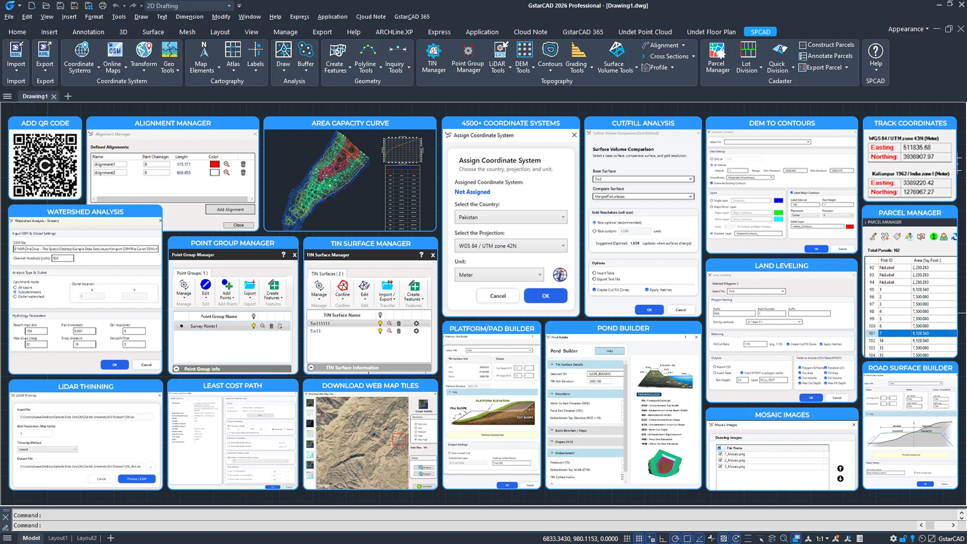
Spcad for gstarcad
The ultimate add-on designed to boost productivity and efficiency. With a robust suite of over 100 tools, SPCAD offers comprehensive CAD solutions, automating tasks while maintaining a high level of accuracy. From assigning coordinates to your drawing to importing/exporting geospatial files, to performing topographic analysis and creating maps and cadaster plans, you can now run spatial analysis without switching to different software.
Key Features- Geospatial Interoperability: SPCAD offers total interoperability with GIS formats, map tiles, and OpenStreetMap data for seamless data exchange.
- Geodetic Precision: Guaranteed accuracy for any project worldwide, supported by a database of over 4,500 coordinate systems.
- Advanced Drafting & Automation: Over 100 specialized commands for high-precision 3D polyline editing, intelligent buffering, and workflow automation.
NEW IN v26.0
- Automated LiDAR Workflows: Streamline your data processing by importing LAS/LAZ files as points or images, with built-in intelligence to automatically extract building footprints and vegetation.
- Dynamic Site Grading: Design complex infrastructure, including slope benches, ponds, and roads, using a grading system that remains fully synced with your TIN surfaces.
- Advanced Terrain Intelligence: Full-cycle terrain analysis that lets you download DEM data, map watersheds, and generate precise cut/fill volume reports in a single environment.
- TIN Surface Management: An overhauled TIN Manager featuring a refined UI to trace water flow, merge surfaces, and label slopes with higher performance.
START YOUR 14 DAYS FREE TRIAL TODAY!
Start your 14-day fully functional trial of SPCAD for GstarCAD today and revolutionize your CAD experience. For more information on installation, visit our help page.
SPCAD is now available on GSTARSOFT!
What’s new in SPCAD V26.0?

Import LAS/LAZ point clouds as CAD points with XYZ and RGB.

Reduce massive LAS/LAZ point clouds into a lighter, faster dataset.

Convert LAS/LAZ point clouds into georeferenced GeoTIFF images for CAD.

Efficiently decompress LAZ files into standard LAS format.

Detect individual trees from LiDAR and insert CAD symbols automatically.

Generate CAD building footprints directly from LAS/LAZ LiDAR data.

Create graded pads on TIN surfaces with defined slopes.

Grade features by distance, elevation, or relative height parameters.

Design pond surfaces using specific slopes, benches, and depth parameters.

Design and place benches along a polyline for slope stabilization.

Generate road surfaces from centerlines with crossfall and width controls.

Download digital elevation models (DEM) for terrain analysis and mapping workflows.

Process elevation data to create and import contours directly into drawings.

Compute optimal routes across terrain using elevation and cost surface analysis.

Generate and analyze hydrologic networks for drainage modeling.

Align DEMs to new coordinate systems and resample grid density.

Inserts map grids according to the current projected coordinate system.

Fetches and inserts online map imagery into your drawing.

Display cursor coordinates in a panel and track multiple coordinate systems.

Manage, classify, and edit points; import/export data; generate contours, hulls, soundings, and tables.

Generates a seamless mosaic by placing images side by side according to their spatial positions.