Display Coordinate System Info into the Drawing
Enhance Your CAD Workflow with SPCAD’s Coordinate System Display Tool
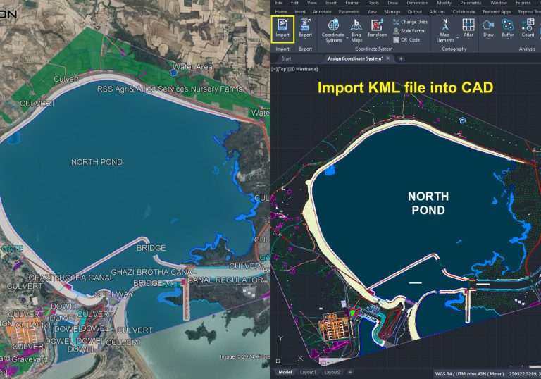
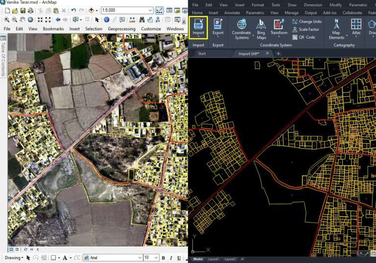
Establishing and documenting a coordinate system is essential for leveraging SPCAD’s powerful analysis tools. These tools include precise measurements of length and area, coordinate transformations, and robust data import/export functionalities.
Why Document Coordinate Systems?
Sometimes, documenting the coordinate system directly on your layouts or maps becomes necessary. SPCAD addresses this need with a specialized tool that extracts and presents all relevant coordinate system information directly on your drawing.
Customize Your Coordinate System Presentation
Our tool offers flexible customization options:
- Select Parameters: Choose which details to include, such as the coordinate system name, projection type, datum, units, and scale factor.
- Format Table: Adjust the appearance of the coordinate system table to match your specific requirements.
Boost Efficiency and Accuracy in Design Documentation
Integrating coordinate system information directly into your drawing ensures consistency and coherence. This approach eliminates the need for external references or additional documents, streamlining your workflow and enhancing overall efficiency.
Practical Benefits for Analysis and Data Exchange
Displaying coordinate system information directly within your drawing also simplifies analysis and data exchange. It provides a clear reference for spatial calculations, ensuring accuracy and minimizing errors.
Conclusion: Maximize Your Design Accuracy with SPCAD
In summary, SPCAD’s coordinate system display tool significantly enhances your CAD workflow. By offering a convenient and customizable method for documenting coordinate system parameters, it improves drawing documentation, facilitates collaboration, and ensures precision in spatial analysis and data exchange.