Create Parcels parallel to the cutting-edge
Creating parcels parallel to the cutting edge in SPCAD is simple and efficient. With SPCAD’s powerful Cadaster tools, CAD users can divide irregular lots into accurate parcels based on equal or custom areas. This guide walks you through each step, from setting up the cutting edge to applying different parcel-cutting techniques for smooth and precise land subdivision.

Initial setup
CAD users frequently encounter scenarios during lot subdivisions where they need to divide an irregularly shaped lot into an array of parcels based on specific or equal area measurements parallel to the cutting edge. SPCAD provides dedicated tools to address such requirements. SPCAD offers a robust tool that guides users to mark the side lot line as the cutting edge during runtime. Any closed polyline can be regarded as a lot.

To begin the process, click on the tool in the Cadaster panel or type DVD_SP in the command bar. Initially, the system will prompt you to select the lot polygon. Once you’ve selected the lot, you’ll have the option to draw a cutting edge along the side lot line.

Make sure to assign a coordinate system to the drawing to avoid triggering a warning like the one depicted. This assignment is crucial for tasks such as area measurement, annotation, and exporting parcels to KML and shapefile.

Cutting Parcels
After obtaining a valid lot polygon, and assigning a coordinate system to the drawing, Click the tool icon or enter DDF_SP. This action prompts the user to select the lot and Draw a cutting edge, after which a GUI will appear. Within this interface, you can independently manage parcel cutting.

Cutting Techniques
In this UI, you can divide a lot into parcels using three methods: By Equal Parcels, By Area, and By List.

- Equal Parcels: Users can specify the desired number of parcels, and SPCAD will divide the lot into that number of parcels, ensuring equal area distribution among them.

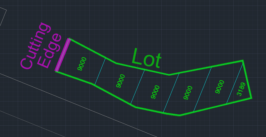
- By Area: Users can specify an area, and SPCAD will divide the lot into parcels, ensuring each parcel meets the specified area. Any remainder from the division process will be adjusted as a separate parcel at the far end of the lot.
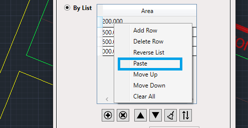
- By List: Users can specify parcel divisions by providing a list of desired distances along the cutting edge. You can add entries, delete, rearrange, or invert within the list interface.

You can access all list operations by right-clicking on the list. Additionally, you can paste lists from other applications (such as Excel or Notepad).

By following these steps and utilizing the various cutting techniques that SPCAD offers, CAD users can effectively manage lot subdivisions with precision and flexibility.