Create Parcels based on the distance along the cutting-edge
To generate an array of parcels with their orientation determined by the distance along a cutting edge, use the ‘Distance Along Cutting Edge’ tool located in the Cadaster tools panel.

Initial setup
CAD users often encounter scenarios during lot subdivisions where they need to divide a lot into parcels based on specific or equal distance measurements along the cutting edge. SPCAD provides dedicated tools to meet such requirements. To begin, users should draw an open Polyline object as the cutting edge.
This Polyline should not be closed and must not be a 3D or 2D Polyline. If the object is a 2D or 3D Polyline or an arc, it should be converted into a Polyline using SPCAD’s ‘Convert to Polyline’ function. Any arc object necessary to mark the entire lot width line or a portion of it must also be converted.
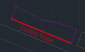
You can adjust the orientation of the cutting edge as needed; it doesn’t need to align with any edge of the lot polygon. However, SPCAD will create the parcels so that they are perpendicular to it,

whereas, a closed polyline will act as a lot.

Ensure assigning a coordinate system to the drawing to avoid triggering a warning like the depicted one. This assignment is crucial for tasks such as area measurement, annotation, and exporting parcels to KML and shapefile.

Cutting options
Once you have obtained a valid lot polygon, a corresponding cutting edge, and assigned a coordinate system to the drawing, proceed by clicking the tool icon or entering DDF_SP. This action will prompt the user to select the lot and the cutting edge, after which a GUI will appear. Within this interface, you can independently manage parcel cutting.

Cutting Techniques
In this UI, you have the flexibility to divide a lot into parcels using three methods:
- By Equal Parts
- By Distance
- By List

- By Equal Parts: Users can specify the desired number of parcels, and SPCAD will divide the lot accordingly, ensuring consistent distances along the cutting edge in front of each parcel. It’s important to note that while the parcels created may not have equal areas, they will all share the same length of cutting edge.

- By Distance: Users can input a distance, prompting SPCAD to divide the lot into parcels. This ensures that each parcel’s front edge aligns with the specified distance, without requiring uniform parcel areas. Any remainder from the division process will be adjusted as a separate parcel at the far end of the lot. It’s important to note that the vertex closer to the selecting cursor during the selection of the cutting edge will be the near end, while the other end will be the far end.

- By List: Users can specify parcel divisions by providing a list of desired distances along the cutting edge. You can add entries, delete, rearrange, or invert within the list interface.

You can access all list operations by right-clicking on the list. Additionally, you can paste lists from other applications (such as Excel or Notepad).

By following these steps and utilizing the various cutting techniques offered by SPCAD, CAD users can effectively manage lot subdivisions with precision and flexibility.


